PJ has now gone off to Sheffield for the next phase of bodywork and paint. This will take a few months to complete and I expect to have PJ back around October 2021. I’m really looking forward to starting to build him back up with all the new, shiny bits I have ready!
Before PJ went away, I spent some time removing parts like the lights and grille from the front end, ready for paint. He’s now ready to go, with his front end riding a little high, without the weight of an engine…
I have a bunch of shiny new carbon fibre parts to fit once the bodywork is done, so I trial fitted some of those parts, to get an idea of how it would look with them fitted. The boot lid will be painted, but the wheel arches and boot floor will remain in clear coat, as will the roof, when it arrives. The boot lid is especially impressive. I have the old boot lid stripped down to just the panel and the weight difference between that and the carbon fibre one is astonishing!
In June 2021, PJ left on the back of a recovery truck, ready for his transformation to begin. When he comes back around October time, he will look quite different, resplendent in his new paint.
For the time being, this is his new home. You can see a few of the other bits, such as the front end and fuel tanks in the background. The big black panel in the bottom left is a whole new bulkhead. We’ve still to decide what’s the best way of putting the bulkhead back to standard; replace the whole lot, or cut out and replace sections.
One thing that did become apparent is that my existing carbon fibre bonnet has sunk on one side. This is worse than I’d thought, so I’ve bought a new one to replace it. The last thing I want to do is have the old one painted and then not be happy with it, so may as well go for a new one. Also the new one from Carbon Weezel is a bit stronger than my old one, so should stand up to the heat a bit better.
Before the shell goes off for bodywork and paint, I wanted to look again at how I have the carbon-fibre front end fastened to the car. Currently, there are two bonnet pins attached to the front of the subframe, which fasten the front panel where the usual rubber mounts would go.
This setup has worked well for many years, however I wondered if there was a way of making this lower mount more subtle and less obviously non-standard. I could of course just bolt it on, making it look just like standard, however I want to retain the quick-release ability of the bonnet pins.
After looking around at all sorts of motorsport fasteners, it looked like some push button bonnet pins might do the trick. The way these work is that the bonnet pin has kind of a ball at the end of it and the fastener grips onto this ball. This is useful, as it allows the fastener a bit of freedom to fasten at a bit of an angle, whereas with a traditional bonnet pin, the panel must fasten at 90 degrees to the pin. Here’s a pic of the pin and with the fastener mounted.
I bought a pair of these push release bonnet pins to try them out and see if they’d be a better option. Because the front panel is curved at the bottom, where the bonnet pins mount, I’d had to make up a spacer previously, to allow the regular bonnet pins to work. Here’s what I mean.
This one was just a trial, but you can see that I’d need to make the aluminium spacer fit the curve of the panel, in order to allow the bonnet pin to fit securely.
Having fitted the new push release bonnet pin to one side of the car, I tried it out to see how well it would work. A couple of problems came to light; firstly, although the push release bonnet pins can work at an angle, that angle is limited and is less than the angle required to match the curve of the front panel. Secondly, it makes it much harder to mount the front end with this style of bonnet pin, as you have to line it up exactly, then push to click it on, which requires some force. Quite a difficult thing to do when you’re holding up the whole front end of the car while you do it. With the original bonnet pins, it’s pretty easy to slide the front end onto the pins, then the pins take the weight as you line everything up and attach the fasteners, making it very simple to attach the front end.
The angle at which the fastener part will grip the pin is limited. This is the maximum angle at which it will grip properly.
Unfortunately, this angle is less than the curve of the front panel where it fastens to the bonnet pin, so I’d still need to make up some sort of spacer to reduce the angle. Once fitted, this style of bonnet pin did look good and was much more subtle than my existing bonnet pins, especially anodised in red. On balance however, I think I’ll stick with the old method, primarily as it’s much easier to mount the front end with the regular bonnet pins.
I may end up using these pins to replace the bonnet pins on the rear edge of the bonnet though, as those are much more visible and would suit this style of fastener better. At least my little experiment wasn’t wasted!
With the engine, subframe and most of the other parts having arrived at the end of November 2020, I made a start on getting the engine trial-fitted into the mini. I’ve now booked the mini in for the remaining bodywork and paint, but it’s not going in until May 2021, so I have a bit of time to do some other jobs.
First thing was to mount the engine and see how it fits. I was originally going to put the engine in the new front subframe and fit it to the car, however I decided to use the old beat-up subframe instead for the trial fit, as that way I won’t risk scratching up the nice newly powder coated subframe.
I hit a minor problem straight away, in that my engine hoist wouldn’t fit under the car, so I couldn’t get the engine close enough to the subframe! This is because the legs of the hoist spread outwards and are too wide, hitting the tie-rods and bottom arms, as you can see in the below pic.
Luckily, this was fairly simple to work around. I just jacked up the front of the car enough that the engine hoist could pass underneath and lowered it again once the hoist was sufficiently far under the car that the legs had narrowed enough to clear the tie-rods.
It was then a matter of getting the lower engine mounts lined up with the holes. At this point, I started to struggle a bit. I just didn’t look like it would fit. To make the holes line up, the engine would have to be moved so far back that the diff housing would hit the rear of the subframe. Then I remembered what Andrew from Vetech had told me when he dropped the engine off. There are two sets of lower engine mount locations on the engine, because there are two different types of front subframe in respect to engine mount positions. Andrew had already attached the engine mounts to the engine in the correct position for my new subframe, but I then twigged that the old subframe I was using must be different. I pulled the engine out again and removed the lower engine mounts, re-fitting them in the alternative locations, which is a simple job. You can see the engine mount and the alternative mounting holes in the pic below.
Once I’d done that, I tried the engine in the subframe again and sure enough it fit like a glove.
Here are some pics of the engine mounted in the car, using the old subframe:
Note that in the pics, the engine is only secured via the lower mounts. This is because I don’t have the mounting points on my bulkhead for one of them, until it goes in for bodywork and the other one I can’t mount because I don’t have the plate fitted where the brake master cylinder lives yet.
Now I have the engine, I want to get the mini booked in for the remaining bodywork and paint as soon as possible. Realistically, it’s going to be a few months before I can get it booked in, but I’ve been thinking about what I want doing when it does go in.
Firstly, I’ll get the wheel arches tubbed, removing some of the rear quarter panel to give more clearance for the wheels when the suspension is under compression, shown by the green line in the pics below.
Existing wheel arches
Green line showing how the panel will be trimmed back
Next, I’ve been thinking what to do with the battery. In a standard mini, the battery is in a box beneath the boot floor, on the drivers side. Locating the battery here makes sense, as it helps to balance the weight of the car by moving a reasonable amount of mass to the rear of the car, balancing out the weight of the engine at the front. Being below the boot floor means the mass is low, helping reduce the centre of gravity of the car and being on the driver’s side balances out the mass of the petrol tank on the opposite side of the boot.
The standard battery box in the boot
Thing is, my car will have twin petrol tanks. The twin tanks means the mass from the fuel tanks will be relatively well balanced across the axle and there will be more mass at the rear of the car (due to the second tank) and less mass at the front of the car (due to the lighter engine). I’d like to move the battery to a new location, which would be a fabricated plinth in the middle of where the rear seat used to be. This will move the mass closer to the centre of the car, though admittedly it will also raise the centre of gravity slightly. The green box in the below pic shows where I’m thinking of putting the battery.
The rear bench, cut back to allow fitment of the roll cage
The green box shows where I’d like to mount the battery
If I move the battery, I’ll no longer need the battery box in the boot. I’m contemplating whether I should have it removed and a steel plate fabricated and welded in, to cover where it used to be, or whether to cut out the boot floor and replace it with a carbon fibre boot floor, like this one from Carbon Weezel.
The bulkhead of the mini was previously modified, with a section cut out and a box welded in to make room for the inlet manifold of the Honda VTEC engine.
When it went in for bodywork previously, the bulkhead box was removed and it now looks like this:
Turns out this is problematic, as where the box has been filled in, it’s had some sheet steel fabricated to fill the gap, but it’s not back to standard mini spec. The issue I have now is mainly with the area in the green box. This is where there would usually be a plate with two holes for the heater hoses and some bolts going through the bulkhead. One of the engine steadies needs to use those bolt holes to mount to and on my car, they’re not there.
To rectify this, I’ll ask the bodyshop to cut out that section of the bulkhead again and weld in a section from a repair panel, so it’s back to how it would have been from the factory.
The other bits I want doing are mainly just tidying up bits of the bodywork that have already been done, but aren’t finished to a very high standard. For example, I had plates welded in to convert the rear lights to mk1 style, but they’re not very tidy:
Also, where the roll cage has had plates welded between the cage and the A-pillars, I’d like the welding filled in and smoothed off, so it looks nice before it all gets painted, as this will be very visible through the windscreen.
Other than those items, it should just be a general tidy up and then paint.
I’ve already decided on the colour – BMW Imola Red II. My biggest worry is about keeping the shell free of marks and scratches when it comes back and I’m building the mini up.
This is a very exciting moment. The assembled engine & gearbox has arrived, along with a whole bunch of other bits, including new front & rear subframes, the exhaust, gear selector mechanism, engine mounts and all sorts of other bits.
Here’s some pics of Christmas come early…
Rear view of the engine
The exhaust system (minus silencers)
New front subframe & a few other bits
The front & rear subframes and a box of bits
Garage emptied, ready for all the new bits!
PJ sat outside, to make room to get the engine into the garage
Front view of the engine, showing the throttle bodies and oil cooler
Now I have the engine, it’s time to get it fitted in the car, so I can measure up for any holes that need to be made in the bulkhead and get it ready to go off for the second part of the bodywork and paint.
I’ve decided that rather than risking scratching or damaging the new subframe, I’ll fit the engine in the old subframe for the measuring up, then just remove it when the shell goes off for bodywork/paint. Then, when the shell’s gone and there’s a bit more space in the garage, I’ll build up the new subframe with the new suspension and brake parts, as well as the engine and it will be ready to mount up to the shell when it comes back.
First, I need to make some small modifications to the old subframe, to allow the engine to fit. That’s the job for this weekend.
It’s been a while since I posted a progress update, as things have been moving quite slowly during the Covid lockdown. Good news though – The engine is almost ready!
It’s taken a bit longer than expected, for many reasons, one of which is that I requested a custom 5th and 6th gear ratio and those gears had to be made by a third party, which took a while. Vetech got the gears a few weeks ago though and started the gearbox build.
The build didn’t go without issues, as the new, larger gears required the gearbox casing to be machined out a little more. Vetech saw to that and soon had the gears installed in the gearbox casing.
Andrew from Vetech has been keeping me updated over the last couple of weeks and things are really motoring now (excuse the pun) with the engine build. Below are a few progress pics that he’s sent.
Now that the build is almost complete, it’s time for me to clear out the garage and make as much space as possible for when it’s delivered. It’s going to be a bit tight in the garage with the mini and the new engine, along with the new subframes and other bits. I’ll remove the rusty old front subframe that’s currently on the mini just to make it a rolling shell and fit the new subframe as soon as I can, so that I can get the old subframe out of the garage and free up a bit of space.
I’m not sure yet whether to bother trial fitting the new rear subframe before I send the car for paint, as I’m not expecting to change anything there. We’ll see how things go with the trial build.
My mini was originally a carb car, which means it had a mechanical fuel pump, rather than an electronic fuel pump in the fuel tank, like the later injection cars did. This means I’d have to either run an external fuel pump in the boot, which get quite noisy, or I’d need to swap the fuel tank out for something else. I thought about a fuel cell in the boot, but I didn’t want to take up all the boot space, so I decided I’d go with a later MPI fuel tank and update the fuel pump for a higher capacity one.
The MPI fuel tank is 7.5 gallons, which isn’t much really. With a more thirsty engine, I was worried about having to fill up every 100 miles if I was on a long journey, so I decided to fit a right hand tank too. The right hand tanks only come in 5.5 gallon capacity, so that would give me a total fuel capacity of 13 gallons, which is much more like it.
My order from Mini Spares arrived and I compared the new MPI tank against my old fuel tank.
The two tanks are almost identical, other than the obvious opening in the top for the fuel pump in the new MPI tank.
One thing that annoys me about several of the parts I’ve ordered is that they don’t come with the required fasteners. For example, with the fuel tank, I ordered a brand new fuel tank and a fuel pump assembly from Mini Spares, but neither of them come with the nuts required to fasten the fuel pump to the tank (see pic below).
What I’ve been doing so far is finding out what size and thread the nuts or bolts are and ordering stainless ones, to keep it looking tidy and avoid rust. It’s not always easy to work out what I need though.
With the new tanks having arrived, I tried them on for size in the mini. One thing that frustrates me is that the left hand tank is finished in gloss black, but the right hand one is matte black. I’ll have to paint the right hand tank in gloss black to match the left one, or it’ll drive me nuts.
I couldn’t get the right hand tank into its final position just yet, as I need to make a hole in the bodywork for the filler neck. There’s also a bracket on the wheel arch, where the windscreen washer bottle mounts. I had to remove the washer bottle bracket and measure, mark up and cut the hole for the tank. That was a scary bit, but I seem to have got it about right.
Having been able to locate the right hand tank in its proper place, I can now see better where the brackets for the tank fitting kit need to go. It’s a bit of a guess, as of course there are no fitting instructions with the kit, but below is where I think the brackets need to go. I’ll try and do a bit more research before I go welding them in, but if you know anything about it, please do get in touch. Any advice appreciated on this bit!
I mentioned to Andrew at Vetech a while back that I was a little concerned about how the Vetech Busa would drive on a motorway cruise. It would likely be revving quite highly at 70mph and I feared the noise might become a bit tiresome on a long journey, as well as high revs putting more stress on the engine. Andrew came up with a couple of options for reducing the engine speed whilst cruising; one is to use a higher final drive ratio and the other is to swap the 5th & 6th gears for a custom pair with taller ratios.
I initially favoured the diff option, as having a taller final drive might make for better traction in lower gears too. Having driven the test cars though, traction is nowhere near as much of a problem as I expected it to be, with both the normally aspirated and supercharged version able to put the power down remarkably well, even on a damp track. I ran some numbers to see what difference the taller final drive and the different ratios for 5th & 6th would make. Here’s what the standard ratios look like (the tyre size is based on 10″ wheels with 70 profile tyres, by the way):
Engine RPM:
5986
Gear Shaft RPM:
3750
Final Drive:
2.84:1
Tyre Height (inches):
19.094
Gear
Ratio
Road Speed (mph)
1st
2.615
28.68
2nd
1.937
38.72
3rd
1.526
49.15
4th
1.285
58.37
5th
1.136
66.03
6th
1.043
71.92
So you can see that at an engine speed of around 6000rpm, you’d be doing around 72mph. I’d like to bring that RPM figure down a bit, to make cruising a bit more comfortable.
Andrew pointed out that the gearbox doesn’t work quite like a regular car gearbox in that the gear shaft does not spin at the same speed as the engine. It uses a reduction gear to spin at around 1.596:1, so you can see the gear shaft spins at 3750rpm when the engine is spinning at 6000rpm.
If the final drive ratio is made a bit taller, at 2.52:1, the figures change to those below (which are based around a cruise speed of around 70mph):
Engine RPM:
5188
Gear Shaft RPM:
3250
Final Drive:
2.52:1
Tyre Height (inches):
19.094
Gear
Ratio
Road Speed (mph)
1st
2.615
28.02
2nd
1.937
37.82
3rd
1.526
48.01
4th
1.285
57.01
5th
1.136
64.49
6th
1.043
70.24
So with the taller final drive ratio, a cruise at 70mph brings the engine speed down to around 5200rpm. That’s certainly an improvement.
If we go back to the original final drive ratio and instead swap the 5th & 6th gear ratios to 1.042 for 5th and 0.81 for 6th, it basically makes 5th gear what 6th used to be and makes 6th gear an overdrive. With those ratios, 70mph in 6th gear brings the engine speed right down to 4550rpm. That’s about what I was looking for and should make a motorway cruise much more comfortable.
As a side effect, it will mean that on accelerating, I’ll drop out of the power band when changing up to 6th gear and to a lesser extent when changing up to 5th. I’m not too bothered about that, as if I was accelerating hard in 4th gear, I’d be doing well over 100mph by the time I needed to change up.
Based on the figures above, I’ve asked Andrew to fit the extended 5th & 6th gear ratios.
I’ve been keeping in touch with Andrew at Vetech and he’s recently been back in the workshop and working hard on my engine. He sent over some photos of the engine strip down and he confirmed that the engine and gearbox seem good, which was a relief!
Here’s some photos of the strip down at Vetech:
And here’s the really impressive bit – the custom machined housing, made by Vetech, sat in the front subframe:
Exciting times! I’m really looking forward to taking delivery when it’s all assembled.
So, things were progressing quite well until around a month ago, but now, most of the significant progress has halted, due to COVID-19.
The main thing that was in progress was the build of the engine and gearbox by VETECH engineering. That was progressing well during February and early March, however, since the lockdown, that work has stopped, as VETECH turn their hand to more important tasks, like making face shields for the NHS. I don’t know how long it will take before they’re up & running again, as that will depend on the spread of the virus and when lockdown restrictions are lifted, but I’m not expecting it to be any time soon.
As well as the engine & gearbox work, VETECH also have my new front and rear subframes, as they’re making some modifications to them for me with their purpose made jigs, before they get powder coated. Without an engine, gearbox or subframes, I’m a bit limited as to what I can get done on the mini.
I’ve been using the time in lockdown to do some planning and to order some of the smaller components that I’ll need soon after the engine/gearbox and subframes arrive. Things like subframe mounts, suspension and brake components, fuel tanks, that sort of thing.
One decision that I’ve been thinking about for some time is what colour to paint PJ once all the bodywork is completed. He’s going to stay red, but I wasn’t sure what exact shade of red. I’m looking for quite a deep red, rather than a bright Ferrari type red. I narrowed down my choice to two shades; BMW Imola Red, or Porsche Carmine Red. I saw a Porsche 991 GTS in Carmine Red at Caffeine & Machine earlier this year and I also saw a BMW E30 M3 painted in BMW Imola Red (the colour wasn’t standard on that car, but the owner had painted it at a later date) at a PistonHeads Sunday Service. Having seen both shades in real life, I decided I preferred the BMW colour. I ordered a couple of rattle cans of Imola Red and I tried them out on my boot lid, to get an idea of what it would look like on the car.
As you can see in the above photos, the finish was a little orange-peely straight after spraying. I’m not sure why that is, I guess I did something wrong, but it’s only a test, so not a big deal. A bit of a MOP with some cutting compound, followed by a regular polish and some wax and it was looking much better, so I tried it on for size on PJ.
You can see the area around the boot lid is all currently finished in red oxide primer, but if you look at the (somewhat dust-covered) front end sat on top of PJ, you can see that the boot lid is a deeper shade of red than the original Flame Red colour that the front end is painted in.
The boot lid will be replaced by a carbon fibre mk1 style bootlid, however I expect my order with Carbon Weezel will be delayed due to COVID-19, so I’m not expecting the boot lid, wheel arches or roof skin to arrive any time soon.
In terms of what’s next, I want to prepare for the arrival of the engine as much as I can. First on the agenda is fuelling. I originally intended to fit a fuel cell centrally in the boot, however as I want to use PJ for long trips to mini shows, including camping, I could really use the boot space not all being taken up by a fuel cell. What I’ve decided to do instead is to fit a 7.5 gallon MPI fuel tank. This can be modified with a higher-flowing fuel pump in-tank, which will reduce the noise compared to an external pump. I’ll then also fit a 5.5 gallon right-hand tank, which will increase fuel capacity to usable levels for longer journeys, whilst still leaving a usable boot space. I have the fuel tanks, fitting kit and balancing pipework on order from Mini Spares, so fitting of the brackets and cutting the filler neck hole for the right hand tank will likely be my next job.
I hadn’t been idle whilst I was waiting for PJ to go in for bodywork. I’d been doing a lot of research into how the VETECH conversion would work and also making plans for lots of other areas of PJ’s renovation.
I kept in regular contact with VETECH engineering, during the conversion’s development and in December 2019, I was the first UK customer to test drive their two demo cars at Curborough Sprint Circuit.
VETECH engineering have two demo cars; the red one is a normally aspirated Gen 2 Hyabusa, with just shy of 200bhp. This car has a sequential gear shift via a gear lever. The orange car has the same basic conversion, but has a Gen 1 Hyabusa engine, which is also supercharged and puts out around 300bhp. VETECH have also recently developed a supercharger kit for the Gen 2 engine. The orange car has no gear lever and instead uses a paddle-shift gear change.
Before I went to the test drive, I was pretty convinced that I’d go for the normally aspirated conversion. I didn’t need the power, or the additional expense of the supercharged version. I was however worried that I’d drive both and fall in love with the more powerful supercharged car. I also expected it to be a real handful and not something I’d want to drive on the road.
When I arrived at Curborough, the track was slightly damp and there were a few spots of rain throughout the day. This wasn’t a bad thing, as it would help me to determine how both cars handled in less than ideal conditions.
I drove the red car first, with the normally aspirated engine. After a couple of fairly slow and steady laps, to get used to the feel of it, I started to ramp up the speed a bit. What impressed me most was how easy it was to drive. I was expecting torque steer and a general lack of grip and traction, but that wasn’t the case at all. Even on a slightly damp track, it handled beautifully and when I gave it too much welly and broke traction, it did so very progressively and controllably. I was frankly astonished at how something so quick could be so friendly to drive.
Next up I tried the orange car. This is the 300bhp supercharged beast and although the red car had behaved very well, I expected this one to be a handful. Again, it wasn’t. Given the track conditions, I wasn’t able to go flat out, as I’d eventually break traction on the damp track if I tried to put all the power down, but I was again very impressed at how well it coped.
What surprised me most was that the red car felt faster than the orange one and was the car that I preferred out of the two. I think there are a couple of reasons for this; firstly, with the slightly damp track conditions, I wasn’t able to fully exploit the potential of either car, so the orange car just had another 100bhp that I couldn’t fully utilise. Also, the red car has throttle bodies with foam filters at the front of the engine bay and most of the noise in the cabin is induction noise. It’s a lovely sound, really addictive and it makes you feel like you’re going faster than you are. The orange car has a plenum, fed by the supercharger and this massively suppresses the induction noise. Because it was so much quieter than the red car, it felt less exciting and made progress so effortlessly that I didn’t notice I was going faster than I was in the red car.
I left Curborough having made a couple of key decisions; I would buy the normally aspirated conversion (I can always upgrade to the supercharger in the future, if I want) and I also wanted the paddle shift gear selector. The gear stick worked well, however I preferred the paddle shift because it frees up some space in the interior by not needing a gear stick, but mostly because you push the gear lever forwards to go down a gear and backwards to change up. This is the opposite of my daily driver and if I got it wrong and changed down a gear rather than up at too high an engine speed, I could over-rev the engine. With the paddle shifts, it’s much more intuitive; right shifter to go up, left shifter to go down. Also, it’s a robotised shift, so rather than being directly connected to the gearbox, it actuates a solenoid via a gearbox ECU. That ECU being between the shift levers and the gearbox means it can make it idiot-proof to a degree and not allow a downshift if it would over-rev the engine.
Just before Christmas, I placed my order with VETECH. The gear lever is simpler to install than the paddle shift, so I’ve ordered that to get me up & running and I’ll upgrade to the paddle shift later on.
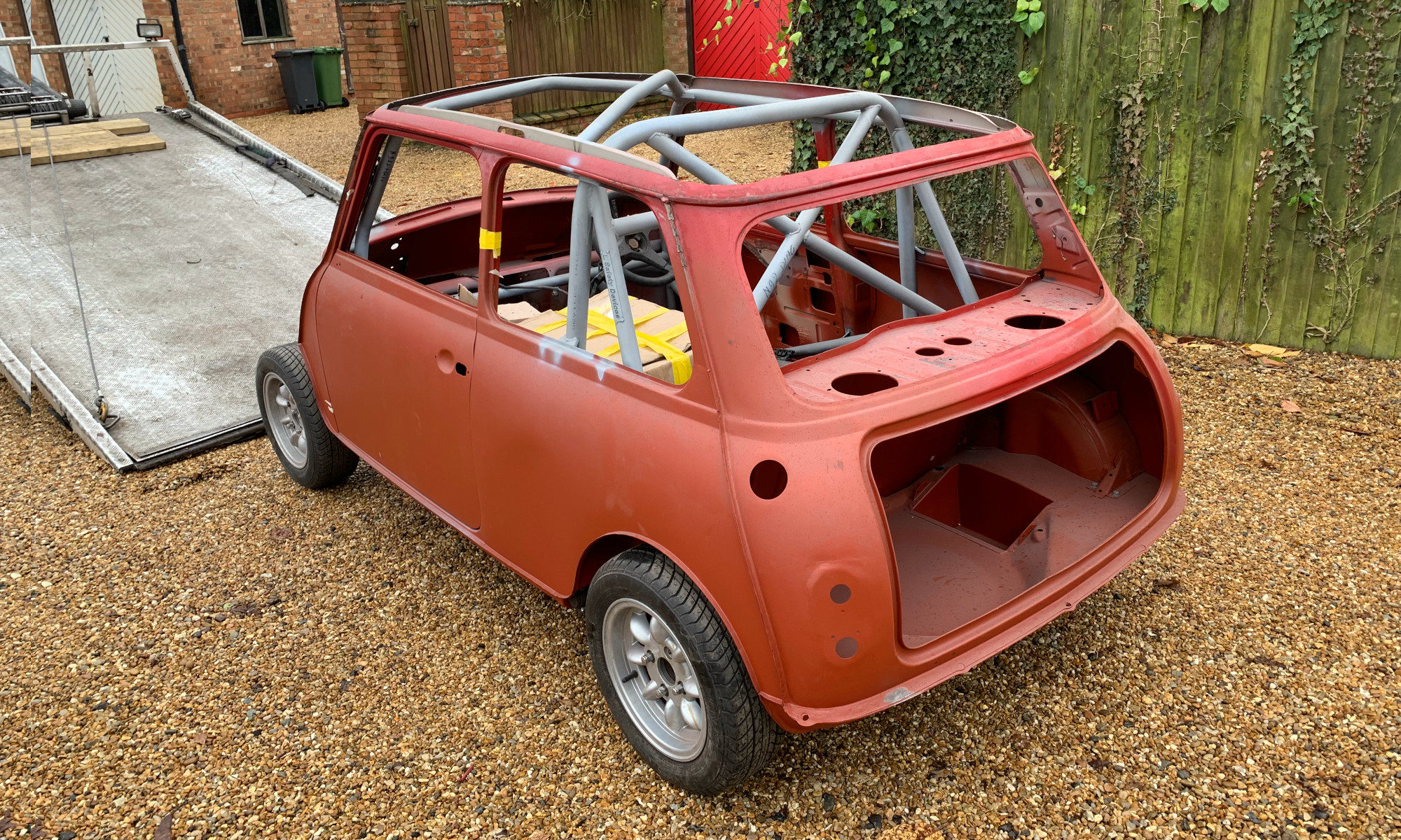
In November, PJ returned from Old Skool Minis, having had quite extensive bodywork completed. Whilst he was there, I got them to install a full weld-in roll cage. I also had some adapter plates welded in to convert from the later style rear lights, to mk1 style.
I decided to bring PJ home before being painted. This way, I can trial fit all the components and make any further alterations that may be required to the shell, before sending him back off for final painting. This way is a bit more hassle, but it would be a shame to have him nicely painted and then go cutting holes or welding him.
Now to decide what colour to paint him. PJ will stay red, but I need to decide exactly what shade.
There ended up being a couple of years pass by before the mini went away for bodywork. I wanted to take it somewhere where I knew the work would be done to a high standard and that meant either Southam Mini & Metro Centre, or Old Skool Minis. I contacted Southam first, as they’d most recently worked on my Mini 40 and I was very happy with their work. They were just too busy though and had a waiting list that kept getting longer, so I got in touch with Old Skool. They also had a long wait for work, but I got myself on the list and waited for my time to come.
Here’s a few pics of the rust on PJ before he went away for bodywork. The bulkhead needed putting back to standard, after I’d modified it for the VTEC inlet manifold, the sills and doorsteps on both sides needed replacing, a new floorpan, drivers side flitch panel, boot floor, rear valance, heel board and some other odds & sods. The boot lid was rusty, but that was no big issue, as that will be replaced by a mk1 style carbon fibre boot lid. PJ also has a sunroof, which I’ve always hated, partly because it always dribbles water down my neck when I go round a left-hand corner when it’s been sat in the rain! I decided I’d have the roof cut off, so I could fit a carbon fibre roof skin.
About six months later, it was time for PJ to go off to Old Skool on the back of a recovery truck. This marked a momentous occasion for me, as PJ’s new life was about to begin!
It wasn’t until 2016, after moving house and selling the Mini 40 that I really decided I was going to put some effort into getting PJ back on the road.
I decided that I wanted to do things properly and that getting it right was better than getting it done quickly. PJ had already sat in the garage for 10 years, so what difference would a couple more make. Turns out I underestimated this slightly!
A lot had changed in the last ten years and things had moved on. The VTEC engine currently sat in PJ was now more than 20 years old and I started to wonder whether going VTEC was still the right thing to do. I started to think about what I really wanted out of my mini and here’s what I came up with:
Power. Not silly amounts, but I wanted a quick mini. Somewhere north of 150bhp, but not so much that it would be unusable on the road
Reliability. I wanted a relatively unstressed engine, not something that was producing way more power than stock and would need rebuilding every 10 hours of use
Usability on the road. I intend to use PJ mainly on (sometimes long) road journeys, with the odd track day, so I wasn’t looking for a race car
Well engineered. I have the money and time to spend on the car now that I didn’t have 10 years ago. I decided I’d rather do things well than do them quickly or cheaply
Something interesting, but understated. I wanted to do something relatively unique, but also understated. Something that at first glance wouldn’t look out of place in a field full of classic minis
I started thinking what my ideal engine conversion would be. Something like the Ford EcoBoost 1.0 was top of my list. Small, light and fairly powerful, easily tunable up to 200bhp. I got wind of a project that Z-cars were working on, making a front wheel drive conversion for exactly that engine. It was perfect, just what I was looking for. The only problem was, it wasn’t available yet. I got in touch with Z-cars, but they were prioritising development of a new bunch of rear wheel drive conversions and the EcoBoost one would come after that. Looked like I’d have to wait a while, but the good news was that it was pitched as a cheaper conversion than their more powerful RWD conversions.
Whilst I was waiting for progress on the Z-cars conversion, I kept looking. I found a company called VETECH engineering, who were developing a Hyabusa engine conversion for the mini, called the VetechBusa. That’s been done before, but what caught my eye about this conversion was that it was front wheel drive, with a proper set up. Driveshaft output through a custom engineered gearbox housing, rather than chain drive. It looked extraordinarily well engineered. I saw they would be attending a mini show at Bingley Hall and I went to see them. I was very impressed!
At this point, I was torn between the EcoBoost conversion and the VETECH conversion. Both seemed like great options, however neither were available yet. After talking to Andrew at VETECH engineering, I’d all but made my mind up to go with the VetechBusa, but my decision was finally made when after speaking to Z-cars, they said the EcoBoost conversion was more difficult than they’d expected and they’d spent so much money on R&D that they were now not going to offer it as an engine conversion package, only as a complete drive-in drive-out conversion, a-la David Brown. That immediately ruled it out for me, partly due to cost and partly because I wanted to do most of the work myself.
My decision was made. PJ was going to have a Hyabusa engine, custom engineered for use in a mini by VETECH engineering.
In late 2005, I parked the mini in my garage and took the key out of the ignition. Half of the key stayed in the ignition. I took this as a sign to take PJ off the road and start on the VTEC conversion that I’d been thinking about for a while.
I bought a donor car in the form of a Honda CRX VTi, which was an MOT failure, primarily due to rust in some structural areas. I didn’t mind about that though, as I just wanted it for its B16A2 engine and gearbox.
PJ before the conversion, with the Allspeed VTEC subframe in the foreground
The donor car, a Honda CRX VTi
The donor car, about to swap places with the mini for its tear-down
It didn’t take me long to tear the Honda apart, selling or scrapping all the bits I didn’t need. I then set about working on making the Honda engine fit into the mini. The Allspeed subframe was designed to make the engine fit in a standard round-nose mini, with no bodywork extensions required. By doing this, the engine sat further back than in some other VTEC subframes, such as the Watsons conversion. This meant I needed to modify the bulkhead to make room for the Honda inlet manifold, as well as modifying the manifold itself. I did quite a lot of work to both the mini and engine/gearbox, including changing the final drive ratio, before it all came to a halt in late 2006, when I moved to Belgium for a few months with work.
When I came home from Belgium at the beginning of 2007, I was at a point where most of the mechanical changes to PJ were done and I needed to make a start on the bodywork, as PJ was by now showing several signs of rust. You can see in some of the images above that I welded in a new windscreen scuttle panel, but other areas were much more difficult and it quickly became apparent that I couldn’t fix the bodywork by myself to the standard that I wanted. I couldn’t afford to pay for it to be done by an expert at the time, so PJ sat in the garage, forgotten and abandoned for the next 10 years or more.
Every now & then, I’d pick it back up again and make a small start on working on PJ again, but it never lasted long, as there were always other things that took over my time. Also, a fatal mistake was that I bought another mini, a beautiful Island Blue Mini 40 (you can see it in the background of one of the pics above). This led to me spending all of my time (and money) on the Mini 40 and very little on PJ.
PJ went through a number of changes over the next few years, including an upgrade to an MG Metro 1275cc engine. I had all sorts of adventures with PJ, including driving all over Europe on my way to the International Mini Meet in Ferrara, Italy in 2003 and in Salou, Spain in 2005.
Having bought PJ, it was time to get him up and running and on the road. I bought a Curley carbon fibre front end and some brace bars, then set about cutting back the inner wings, fitting the front end and tidying up the rest of the car.
I’ll start with a little of the back story behind PJ and his journey so far, before I start with the current restoration work.
I bought PJ in 2002. I’d just crashed my previous mini “MOL”, which was my first car and I was looking for a 998cc mini (cheap insurance) to replace it. I’d already decided that this mini would have a removable front end, to give me more space when working on the engine and I stumbled across a car available locally that seemed perfect.
It had a rusty front end, which had already been cut off by the previous owner, ready to have new panels welded on, but ended up being sold as a part finished project. This was perfect for me, as I wanted to fit a carbon fibre front end anyway, so I bought it and that’s where the story starts. Here’s some pics of PJ when I bought him…